原文地址:https://fuse.wikichip.org/news/567/iedm-2017-intel-details-22ffl-a-relaxed-14nm-process-for-foundry-customers-targets-mobile-and-rf-apps/
原文作者:David Schor
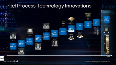
In March of this year Intel announced their 22FFL process. At the 63rd IEEE International Electron Devices Meeting (IEDM), Intel presented their highly anticipated paper on this process technology. The paper was presented by Dr. Ben Sell, integration manager at Intel.
Overview
While Intel’s regular process technology is geared toward high-performance chips, there is a growing need for a different process that is optimized around a different set of features such as ultra-low power, RF performance, and low design and wafer cost. With those optimizations in mind, Intel developed a new technology called “22 nm FinFET Low Power” or “22FFL” for short. Despite its name, 22FFL borrows more from Intel’s 14nm than it does from their 22nm process. In other words, 22FFL can be thought of as a relaxed 14nm process optimized for mobile and RF applications. “We started with our 14-nanometer transistors and improved from there,” Ben said.
Features
The primary features of Intel’s 22FFL are:
Low-cost ? overall low wafer cost as well as ease of use which lowers designs cost
High-performance ? 14nm transistors were the starting point, adopted for this process
Ultra-low leakage ? special transistors with much lower total leakage than what Intel normally uses for their own technologies
Low Vmin ? Support for low Vmin was needed for reducing the active power
For analog, RF, and I/O functionality 22FFL also features:
Low noise analog
High voltage
High frequency RF
Simplified Metal Stack
For their own products, Intel uses a highly advanced metal stack that offers very tight interconnects that are both complex and expensive to design. 22FFL offers a very simple metal stack with relaxed metal pitches meaning a single-pattern backend flow that reduces cost and is highly flexible and easy to use.

Cross section of the 22FFL Metal Stack
The image above shows the standard 22FFL metallization stack. At the bottom are the transistors on top of which are 6 metal layers with a 90 nm pitch. On top this Intel added two thick metal layers ? one with a 1,080 nm pitch and one with a 4-micron pitch. For some applications, adding intermediate layers between the M6 and M7 is very beneficial which is why they offer 2x, 4x, and 8x layers as options.
The two upper layers are designed for global routing. Note that upper-most layer (M8) has a second function ? it was specifically designed to be very good for building high-Q inductors (discussed later in this article). Between the M8 and M7, there are the metal-insulator-metal (MIM) capacitors that are used for decoupling the signal capacitance.
Overall, the backend metallization stack is shown below.

High-Performance Logic (FinFET)
For the high-performance transistors Intel started with their 14nm process FinFET transistors and modified them to suit this new process. Below is a cross sectional view of the fin. What’s immediately clear is that those are Intel’s 14nm very straight fins (their 22nm had trapezoidal fins). The 22FFL fin pitch is slightly relaxed at 45nm (vs 42nm for the 14nm process).

22FFL logic fin cross section
Below is the gate cross section. 22FFL still uses a high-κ metal gate with a strained channel process.

22FFL gate cross section
The gate pitch has been greatly relaxed in order to run multiple channel lengths. In case you’re wondering, those dimensions are Lg = 32nm for ULVT and HP, Lg = 36nm for LVT and Nom, and Lg = 44nm for LPLVT and LP. Below on the left are the IDS-VGS curves for those logic devices for both nMOS and pMOS. The figure shows well-behaved devices with a very good DIBL and subthreshold slope. In fact, since the channel effects are so good, they do not get much leakage modulation from the channel lengths so a second work function is used to target the threshold voltage of the remaining devices. This is shown on the second graph on the right.

22FFL IDS-VGS curves demonstrating low DIBL and subthreshold slopes
Shown below is the comparison of 22FFL to previous process technologies. FinFET was first introduced by Intel at their 22 nm node which resulted in a much closer to ideal subthreshold slope however once you get down to a very short channel you start to see a sharp increase. With 22FFL, even at the shortest gate lengths (i.e., 32 nanometers), Intel still reports 63 mV/dec subthreshold slope meaning very close to linear. With 22FFL intel offers analog devices and those feature a much larger gate length of up to 160 nm. Those analog devices stay at around 60 mV/dec.

Channel length short gates subthreshold slope compared to previous technologies
At 0.7 volt, Intel reports 1.29 mA/μm for pMOS and 1.38mA/μm for nMOS for their highest performance devices. Compared to their own standard 22 nm technology, there is a significant improvement in drive current for both pMOS and nMOS. For pMOS Intel reported 87% increase in drive strength and 57% increase for nMOS. Note that for the low-leakage devices (shown in purple and blue on the graph below), 22FFL has considerably higher drive current and lower leakage vs. what they had for their standard 22nm process.

nMOS and pMOS IDsat vs. Ioff for 22FFL vs Intel’s original 22nm process
Ultra-Low Leakage
The performance we talked about earlier is for the standard 22FFL devices which had a fin pitch of 108nm. In addition to those devices, Intel introduced 144nm pitch devices for ultra-low leakage. 22FFL ULL devices have sub-1 picoamp per micron total leakage. Those devices provide up to an additional 75x reduction in leakage.

In the graph above, Intel’s original 22nm process (on the upper-left corner) can be used as a reference. The high-performance 22FFL devices start at the very top-right corner. Those six points represent the six devices we mentioned earlier (LP, Nom, HP, LPLVT, LVT, ULVT). There is a range of over 500x between the highest- and lowest- leakage among those devices. The Ultra-low leakage devices can offer an additional 75x reduction in leakage. We believe those are among the lowest, if not the lowest, total leakage logical devices reported with sub 1-picoamp per micron leakage.
Device Summary
We have summarized the three types of logic devices offered by Intel’s 22FFL.

SRAM
As expected, a number of SRAM bit cells were developed for 22FFL. At their 2017 IEDM presentation Intel reported three cells: high current cell (HCC), high density cell (HDC), and a low leakage cell (HCC-LL). For the HCC SRAM, which is a modified 14nm SRAM, Intel reported a cell area of 0.087 μm? and a low Vmin of 490 mV. The HCC is a slightly bigger cell, reported at 0.107 μm?. But if you’re willing to pay for a little bit more area and a bit higher leakage, you get much higher current and even lower Vmin (reported at 440 mV which is actually one of the lowest Vmin reported to date).
The HCC-LL SRAM is based on the ultra-low leakage device with a bit cell leakage of sub-picoamp per bit. Since the Vth is higher for this cell, the Vmin is also higher but has been reported to be around 720 mV. Note that the cell area was not reported.

For the graph above Intel’s figure of merit is at the Vmin at the 95 percentile. Those values were obtained based on 9000 dies of 16 Mib and 32 Mib 6T SRAM arrays at worst case after stress testing.

Analog Devices
The good logic characteristics also transfer to analog transistors. Intel presented three analog devices. Since the Rout is proportional to the channel length, those three devices have channel lengths of 144nm, 216nm, and 270nm.

For their longest channel length devices with 6 fins Intel reported an Rout of 0.68 MΩ. In the graph above, the black points are Intel’s previous technologies. They use GM * Rout as a way of comparing the performance of their transistors. The first few red points are actually the logic 22FFL devices which also have a better GM*Rout then their old technologies but for the analog devices with much bigger channel length the improvement is pretty substantial.
At IEDM they presented a PLL which was designed with those analog devices. At 3.2 GHz output frequency and 0.85 volt Intel reported 0.77 mW of power. An almost identical device was actually presented a few years ago at IEDM for their 14nm process. Compared to the PLL device implemented on their 14nm, the 22FFL PLL gets much lower power for roughly the same jitter.

I/O Transistors
22FFL offers I/O transistors which operate at the higher voltage of 1.8 volts. Those transistors are very similar to the logic devices. They have a straight fin with an identical pitch of 45 nm consisting of a high-κ metal gate with strained channel process. Those devices use a gate length of 160nm. Below is the cross section of the fin shown in the left image and a cross section of the gate on the right.

Three thick gate devices were developed to support 1.8 V, 1.5 V, and 1.2 V operations. Those transistors have gate length of 90 nm, 120 nm, and 160 nm respectively (for comparison LL logic Lg = 74 nm). For those devices Intel reported very good drive currents which are considerably higher than what they had in their previous 22m technology. For nMOS they reported around 1.11 mA/um and for pMOS it’s around 1.02 mA/um for the highest voltage cells.

Overall, drive current for 22FFL high voltage transistors are roughly 33% for nMOS and 35% for pMOS over their original 22nm process.
Device Summary (Analog and I/O)
We have summarized the six types of analog and high voltage devices offered by Intel’s 22FFL.

RF Devices
One of the more important aspects of 22FFL is its RF characteristics which Intel clearly spent a lot time enhancing. The graph below shows FT (in GHz) has a function of gate-source voltage. At IEDM they presented an RF standard device on 22FFL which is shown in the open circles. It shows a good balance between nMOS and pMOS with around 180 GHz for nMOS and around 190 GHz for pMOS. Based on that standard device, they also presented an improved high-density device which is shown in the shaded circles. This device reached 238 GHz for pMOS and 230 GHz for nMOS. Ben explained that they plan on improving this device further where they expect to deliver a high-performance device which can go above 300 GHz in their next round of improvements. The projected high-performance RF device is shown in black on the graph. It’s worth noting that all FT values do include parasitic RC up to the Metal 2 layer.

FT as function of VGS
In order to compare their 22FFL RF devices with their older technologies, they presented a plot of FT over GM/ID. GM/ID is a figure of merit that Intel’s RF designers use which should be around 10 or higher. Values less than 10 mean the device is wasting too much power resulting in a very inefficient design. In other words, it’s not enough to just compare the maximum FT of the device, we must consider how much of that is usable in practice.

The black line on the graph is a 32nm planar RF device featuring a reported device with an FT of 305 GHz. However when plotted against GM/ID it’s pretty clear that much of it isn’t very good for efficient designs. In fact the highest usable FT, or the highest FT that falls within a GM/ID of 10 or higher, is actually around 165 GHz. Therefore, despite being called a 305 GHz device, the actual usable FT is only around half of that value at around 165 GHz. On the other hand, for the 22FFL RF device, despite having a max FT of 230 GHz, much of the curve falls within a GM/ID of 10 or higher making the highest usable FT somewhere around 205 GHz.
A similar explanation was given for the FMAX of their RF device. The starting standard RF device delivered an FMAX of 242 GHz for pMOS and 284 GHz for nMOS. That’s shown on the graph below in open circles. They improved the process further which resulted in an FMAX of 290 GHz for pMOS and 357 GHz for nMOS.

Much of that improvement came from reduced gate capacitance and reduced gate resistance.
As with the FT, Intel plotted the FMAX over GM/ID in order to show the acceptable design region (10 or greater).

On the 32nm planar process you can make an RF device with a max FMAX of around 295 GHz, however the usable FMAX for that device is only around 210 GHz when within the acceptable design region. When compared to the 22FFL RF device which has a max FMAX of around 284 GHz, we can see that almost the entire peak of the curve falls within the design region with a usable FMAX of 270 GHz.
Metal 8, Good for Inductors
Earlier, when discussing the metallization stack, we mentioned that the upper-most layer (M8) had a second function. It was designed to allow for the design of high-Q inductors. To demonstrate this, inductors of different sizes were tested in order to determine the size for the best quality factor. Below is the inductor layout cell which has a very simple design and was fabricated on the Metal 8 layer.

Inductor cell layout fabricted on the Metal 8 layer
The graph below on the left shows the inductance for the various lengths.

Inductance and Quality Factor for various size inductors.
As expected, by increasing the coils diameter or making the core longer, we increase inductance. However the when you compare those sizes against the graph of the quality factor, it’s clear that the 175-micron inductor (in blue) has the highest differential quality factor of over 30 Q.
22FFL
Intel’s 22FFL IEDM presentation was much more detailed but we think we touched on most of the important points.
Unlike their own advanced process which has draconian design rules, 22FFL is specifically designed for their foundry customers with low-cost and ease of use first and foremost. They offer high-performance transistors which are a relaxed version of their 14nm process which offers 57% nMOS and 87% pMOS drive gain over their own 22nm. They also also offer ulra-low leakage devices with sub 1-picoamp per micron leakage. They demonstrated SRAM of various designs including a record low SRAM Vmin cell. Additionally, the technology offers high-voltage (1.8V) transistors for I/O with >1mA/um and RF devices with FT / MAX of over 230 GHz and 290 GHz.

22FFL Devices Summary from Intel’s Tech Day
A Change of Plan? Going 6T
Just before publishing this article we went over our notes from Intel’s Technology and Manufacturing Day which was held back in March. What caught our eye was the following slide:

22FFL Dimensions from Tech Day
We have highlighted in red the three interesting dimensions ? a 7-track logic cell with a height of 630nm, an SRAM of 0.88 μm? and a density of 18.8 MTr/mm?. What they presented at IEDM was 6-track logic cells with a height of 540nm, and SRAM of 0.87 μm? which implies a density of well over 20 MTr/mm?. That’s a fairly large change from the initial March values to what was presented at IEDM.
Conclusion
Over the last few years, Intel has been trying to grow its custom foundry business. In the past year we have seen a much more aggressive push with the announcement of their custom foundry 22FFL and 10nm HPM/GP technologies. Intel has stated that their 22FFL FinFET technology is cost competitive with other pure-play planar 22nm and 28nm technologies. Overall 22FFL seems to be an excellent process for low-cost, high-performance mobile and RF applications. PDK 0.5 was available as early as April of this year with PDK 1.0 introduced not too long ago. We expect 22FFL to be production-ready in the very near future. Customers will be doing their own analysis and run their own simulations and benchmarks and make their own educated conclusions. Only time will tell if they succeed in attracting new foundry customer.

22FFL Ecosystem